Power combiners: How to define your needs?
When looking for a power combining solution, it is primordial to define specifications as close as possible to your needs. Indeed, dealing with high power leads to a high risk of serious failure. On the other hand, for low power applications, maximizing cost efficiency is important for your system to be competitive. In this technical note we will guide you through the basics you need to know when looking for a new power combiner.
According to the frequency range needed Deti can provide you 5 major types of power combiners:
Topology
Gysel Power Combiners
Gysel power combiners are great for narrow band (< 1 octave) high power and high mismatch power applications. It can be used a 2/4/8/16-way configuration.
Wilkinson Power Combiners
Wilkinson is the most commonly used topology thanks to its versatility. Indeed it can be used to design very wideband products. It can also handle a lot of power and mismatch with a proper design. The main issue is that it can be quite big in lower frequency range.
Radial Power Combiners
Radial power combiners are mostly used in narrow band application and are often non isolated, as their star shape leads to tricky design challenges when trying to integrate internal loads. However, it is the most versatile topology in term of number of inputs and can easily handle a lot of power.
Toroidal Magnetic Core Power Combiners
One of Deti specialty. For now, it is only available in a 4-way configuration. This unique technology allows ultra-wide bandwidth especially at low frequency and can deal with a tremendous amount of RF power (up to 16 kW CW).
Waveguide Magic Tee Power Combiners
They show the same pros and cons as traditional waveguide structures. Indeed, Waveguide Magic Tee Power Combiners can handle a lot of CW and peak power but on a limited bandwidth. Furthermore, they show a large size and high cost, but in some applications, it is the only way to go.
Parameter definition
Continuous power handling
CW Power handling is limited by the technology used for the design. Indeed, in order to define it, the main parameter is insertion loss. In physics terms insertion loss represents the amount of power that needs to be dissipated as heat. It is why some of our products needs heat sinks or forced ventilation to handle high power.
When calculating the power handling, power reflected by the load used at the output needs to be taken into account. Indeed, if the output of the power combiner is a short circuit or an open circuit, all the combined power stays within the product. That’s why most our products are rated for a 1.2:1 VSWR output load. Custom value of output load can be achieved on demand (from 1.2:1 to any load).
Peak power handling
Peak power handling leads to 2 distinct problematics:
- Equivalence with CW power handling as it can be approximated to Peq_cw=Ppeak x Duty Cycle, which lead similar issues as in the CW power handling paragraph.
- Peak power value it self that need to be consider as it can lead to electrical shorting if the distances between the high power signal and the ground are not properly taken into account.
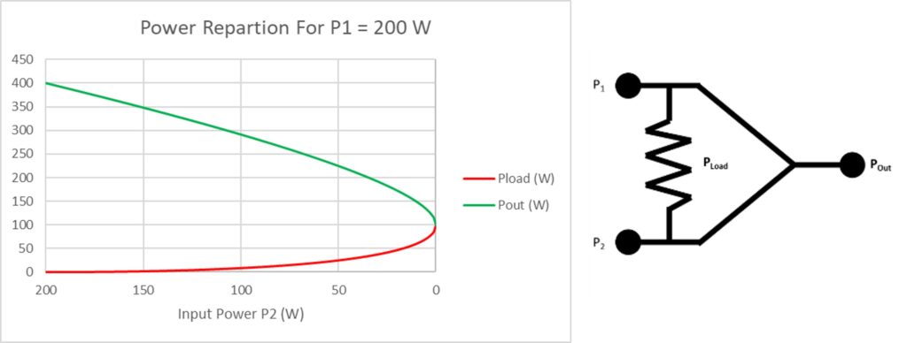
Power input mismatch
The input mismatch admissible by a power combiner is mainly dependent on the internal load power handling. As shown on the figure below, the power viewed by the loads is rapidly increasing as the input power mismatch increases. If one input power is 0 W(full input failure), then half the power is going into the load and half is outputted. Please note that most of our design can support a full input failure for a couple a second, in order to give time to the other inputs to shut down properly.
Phase balance between the inputs also has to be taken into account even if, as shown below, it is only critical for high phase differences:
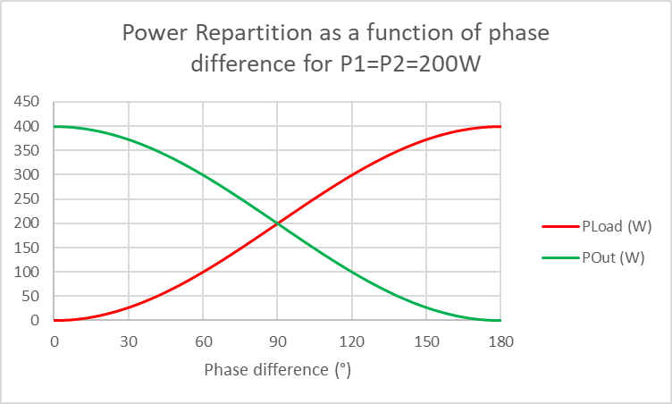
However, in a few cases, full input failure has to be a normal operation state. In this figure case, we can design custom products that can handle it in a continuous way.
Isolation
The isolation is the amount of power transmitted from one input to another. The higher the isolation is, the least power is leaking between Inputs. This allows a protection between the power sources.
Phase and amplitude balance
In an ideal power combiner, all ways are strictly equivalent and therefore there is a perfect balance between each way. But because perfection doesn’t exist there is always small differences between ways. In order to maximize the output power, we need ways with the lowest amplitude and phase balance.
VSWR
The VSWR represents the amount of power reflected, it is also sometimes referred as return loss in dB. Low VSWR are most easily attainable with a narrow band and a limited number of ways. When dealing with more elaborate design (large frequency range or for 8+ ways power combiner) it becomes trickier to minimize the VSWR.
Environnemental contraints
When a power combiner is used inside a lab or on a EMC testing site, its environment is quite stable, and therefore doesn’t need to be taken into account when looking for a new product. However, in some applications such as Electronic Warefare or Satcom Ground Station, it needs to be used in more challenging environments. Here some examples of environmental constraints that you need to define:
Mechanical shocks, thermal shocks and vibrations
Even if these 3 are different parameters they are taken into consideration during the design process as the effect is stress on internal parts of the product.
Humidity
When a product is used in a damped environment, painting and/or seals need to be used in order to make the product hermetic. Therefore prevents the humidity to get inside the product, potentially damaging it.
Operating temperature
This constrains need to be looked at on two different angles:
- As the product temperature varies, it creates a variation in dimensions which can lead to a frequency shift of the performances. Please note that all our power combiner specifications are valid on the operating temperature range specified on the datasheet.
- When the temperature raises, it become harder to evacuate the heat out of the product, therefore our product can often handle more power at room temperature.
Atmospheric pressure
When the product is airborne, the pressure drops as a function of the altitude. It impacts its power handling and therefore needs to be specified.