Product Discussion : Directional couplers
A directional coupler inserted in a transmission line allows precise monitoring of the RF energy flow in that line while introducing minimum perturbations of the main line signal in the sampling process. Directional couplers are designed for monitoring incident and reflected power supervision.
Directional couplers are available in different classes :
- Three port directional couplers
- Four port bi-directional couplers
- Four port, dual directional couplers
Three port directional couplers
Three port directional couplers, as illustrated in Figure 1, are four port networks where one port is internally terminated in a resistive load thus becoming the isolated port. the other three ports are :
1. Main line input port
2. Main line output port
3. Coupled output port
Figure 1 : Three port directional coupler
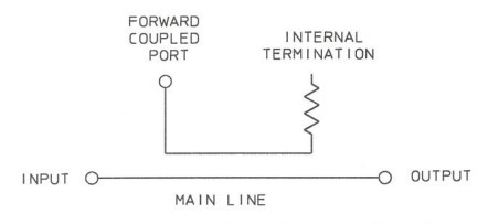
An RF signal applied to the input port splits unequally between the coupled port and the main line output port. The degree of unequal power division is a function of the coupling ratio of the coupler.
The isolated port, commonly known as “load port” is designed to absorb and dissipate reflected energy in a “failsafe” mode. This termination will survive when open or short circuit conditions occurs at the main line output port, while operating to the maximum average input power rating. The power dissipation capability of the internal termination is the major factor determining maximum reverse power ratings.
Four port bi-directional couplers
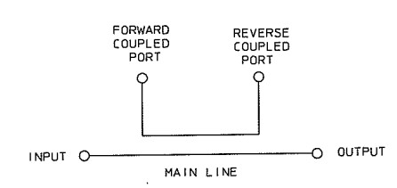
The four port network (see Figure 2) has the isolated port externalized with either an RF connector or pin. One advantage of this type of coupler is that a higher power termination can be selected to suit higher input power requirements. The four port network can also be used as a bi-directional coupler in order to monitor signals in both directions.
Figure 2 : Four port bi-directional coupler
Dual directional couplers
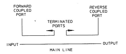
Dual directional couplers (see Figure 3) are four port networks that are distinguished from the bi-directional types in that dual directional couplers are two independent four port networks connected in series. Their principal application is monitoring signals simultaneously in both directions (foward and reverse). They are preferred over the simple bi-directional coupler in that they provide higher isolation between coupled ports. Furthermore, the coupling value can be different between the foward and the reverse direction.
Figure 3 : Four port dual directional coupler
Coupling values
Couplers are available in 6, 10, 15, 20 or 30 dB coupling values. High power units are cataloged from 30 to 50 dB values.
Transmission loss
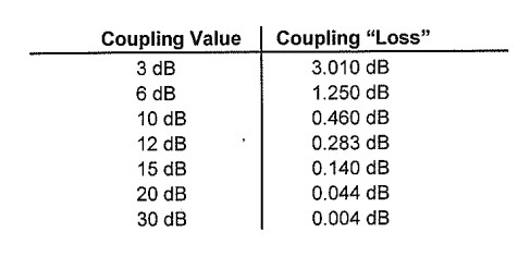
To determine total loss through the main line of a directional coupler, the coupling loss (power directed to the coupled arm) must be combined with the insertion loss. Coupling loss is a function of the coupling value utilized. Coupling losses of standard couplers are shown in Table 1.
Table 1 : Coupling value and coupling loss
Parameter definitions
Nominal coupling
The power ratio in dB by which the coupled output port is uncoupled from the input port when all ports are terminated in reflectionless (matched) terminations. The nominal coupling is specified as the arithmetic average of the maximum and the minimum coupling within the frequency band.
Coupling flatness
Sometimes call frequency sensitivity, it is the peak-to-peak deviation in dB from the nominal coupling over the specified frequency range.
Insertion loss
The net unrecoverable power in dB dissipated within the circuit at any frequency within the specified range. The insertion loss is usually specified as excluding the coupling loss, but to avoid a complex and perhaps critical calculation, it is expressed as including coupling loss for dual directional and high power models.
Coupling “loss”
The main line signal loss in dB attributable to power being sampled at the coupled port.
Transmission loss
The sum of the maximum insertion loss and coupling “loss” in dB at any frequency in the specified range.
Directivity
Expressed as a power ratio in dB, directivity is a measure of the preferential coupling of RF energy from the mainline to the coupled port in the “forward” direction compared to that in the “reverse” with all ports terminated in matched (reflectionless) loads.
VSWR
The voltage standing wave ration specified for either the main line path (input to input) and/or the coupled output port(s).
Average or CW power capacity
The CW power handling capacity is the one-way power transmission capacity through the device under matched load conditions.
Directional couplers applications
- Directional couplers are used to accurately sample the directional power flow in a transmission line. In conjunction with a calibrated detector or a power bridge, an accurate, continuous measurement of power flow can be obtained. In this function directional couplers can be an essential part of system BITE (built in test equipment).
- Power leveling can be performed when the coupled output of a directional coupler is used in conjunction with a modulator or a PIN attenuator as a part of a leveling loop.
- Frequency measurement can be made on continuous basis when the coupled sample is fed to a suitable frequency counter or equivalent.
- Frequency stabilization can be obtained when the coupler output is used as the input to an AFC (automatic frequency control) loop.
- Continuous power reflection measurements such as might result from antenna misalignments can be made using couplers as reflectometers. The power source is fed to the main line output port and the coupler main line input port is connected to the load (antenna). reflected power will thus be coupled to the forward coupled output where it can be monitored.
- Signal injection can be obtained by feeding the injectable signal into the mainline via the coupled port. The direction of the inserted signal power flow depends on the coupler polarity in the transmission line.